NAME
IUP::MglPlot - [GUI element] canvas-like element for creating 2D plots (based on MathGL library)
DESCRIPTION
Creates a MathGL based element for creating 2D and 3D plots with interface similar to IUP::PPlot.
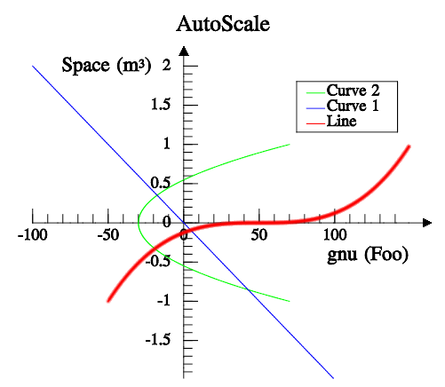 |
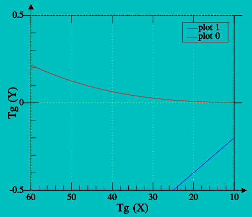 |
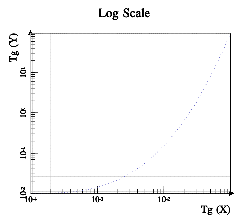 |
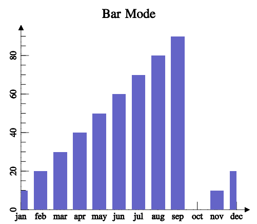 |
USAGE
CREATION - new() method
$plot = IUP::MglPlot->new( TITLE=>"Simple Data", GRID=>"YES" );Returns: the identifier of the created element, or undef if an error occurs.
NOTE: You can pass to new() other ATTRIBUTE=>'value' or CALLBACKNAME=>\&func pairs relevant to this element - see IUP::Manual::02_Elements.
Guide
Each plot can contain 2 or 3 axes (X and Y and/or Z), a title, a legend box, a colorbar, a grid, a dataset area and as many datasets you want.
Each dataset is added using the PlotAdd1D, PlotAdd2D, PlotAdd3D, PlotInsert1D, PlotInsert2D, PlotInsert3D PlotSet1D, PlotSet2D and PlotSet3D functions. All other plot parameters are configured by attributes.
If no attribute is set, the default values were selected to best display the plot.
IMPORTANT: When setting attributes the plot is NOT redrawn until the REDRAW attribute is set or a redraw event occurs.
The dataset area is delimited by the min/max axis attributes. Data is only plotted inside the dataset area. This area defines the 2D or 3D plot coordinate space. The screen area is a 2D pixels coordinate space. And finally the dataset also defines a normalized space, that means min/max is converted to 0-1.
The legend box is a list of the dataset names, each one drawn with the same color of the correspondent dataset. The box is located in one of the four corners of the dataset area.
The colorbar is an additional axis showing the the colors used to pseudo color the data for some plot modes.
The grid is automatically spaced accordingly the current axis displayed values.
The title is always centered in the top of the plot.
The axes are positioned at the origin (0,0,0), but can be automatically positioned at the left-bottom. If values are only positive then the origin will be placed in left bottom position. If values are negative and positive then origin will be placed inside the plot. The ticks in the axis are also automatically distributed.
Data
MathGL supports several kinds of data. IUP::MglPlot restricts this to a few combinations. First there are 3 major classes:
Linear sequential data are simply a sequence of points whether in 1D, 2D or 3D coordinates.
Planar data is a bi-dimensional array of values, just like a digital image. Each value is
f(x,y), wherexbelongs to[-1, 1]andyto[-1, 1].Volumetric data is a tri-dimensional array of values, that represents a 3D volume. Each value is
f(x,y,z), wherexbelongs to[-1, 1],yto[-1, 1]andzto[-1, 1].
Planar and volumetric data can be very memory consuming, so be careful when using them. Linear data is the same representation accepted by IUP::PPlot, with the exception that IUP::MglPlot has support for 3D coordinates. Also planar and volumetric data in IUP::MglPlot have x, y and z coordinates equidistantly distributed from 0 to count-1.
Planar and volumetric data are stored in a 1D dataset created by PlotNewDataSet, and filled with PlotSetData, PlotLoadData or SetFromFormula functions only.
Interaction - Zoom and Pan
Zoom and Pan operations can be done using keyboard or mouse actions in 2D and 3D plots.
Zoom can be done using the mouse wheel (Zoom in: scroll up; Zoom out: scroll down), the Ctrl+Left mouse button pressed and vertical mouse movements (Zoom in: bottom-up; Zoom out: top-down) or the plus '+' (Zoom in) and minus '−' (Zoom out) keys.
Pan is done using horizontal and vertical mouse movements with the left mouse button pressed. By keyboard, the Ctrl+arrow keys combinations can be used to shift the window. Arrow keys can also be used without using the Ctrl key to slower movements.
Interaction - Rotation
Rotation operations can also be done using keyboard or mouse actions, but only for 3D plots.
Rotation in X axis: right mouse button pressed and vertical mouse movements, or 'w' and 's' keys.
Rotation in Y axis: right mouse button pressed and horizontal mouse movements, or 'a' and 'd' keys.
Rotation in Z axis: Ctrl+right mouse button pressed and vertical mouse movements, or 'e' and 'q' keys.
Interaction - Reseting
The interaction can be reset with a mouse double-click inside the plot area or by pressing the HOME key. This action restores the plot to the default view (no zoom, no pan and no rotation).
Text and Fonts
MathGL provides support for parsing LaTeX-like syntax. So all labels and title can contain formatting commands and equation symbols. For example: \b (bold), \i (italic), \u (underline), \big (bigger size), @ (smaller size), ^ (upper), _ (lower), etc. The full list contain approximately 2000 commands. Multiline text is accepted.
For example:
"It can be \\wire{wire}, \\big{big} or #r{colored}"
"One can change style in string: " "\\b{bold}, \\i{italic, \\b{both}}"
"Easy to \\a{overline} or \\u{underline}"
"Easy to change indexes ^{up} _{down} @{center}"
"It parse TeX: \\int \\alpha \\cdot \\sqrt3{sin(\\pi x)^2 + \\gamma_{i_k}} dx"
"\\sqrt{\\frac{\\alpha^{\\gamma^2}+" "\\overset 1{\\big\\infty}}{\\sqrt3{2+b}}}"
Auxiliary Functions
PlotBegin()
$plot->PlotBegin($dim);
# $dim = 1 (for 1D) or 2 (for 2D) or 3 (for 3D)
Prepares a dataset to receive samples. The dimension of the data can be 1, 2 or 3. Linear data only.
PlotEnd()
$index = $plot->PlotEnd();Adds the dataset to the plot and returns the dataset index. The dataset can be empty. Redraw is NOT done until the REDRAW attribute is set. Also it will change the current dataset index (CURRENT) to the return value. You can only set attributes of a dataset AFTER you added the dataset. Can only be called if PlotBegin was called. Whenever you create a dataset all its "DS_*" attributes will be set to the default values. Notice that DS_MODE must be set before other "DS_*" attributes. Linear data only.
PlotNewDataSet()
$plot->PlotNewDataSet($dim);
# $dim = 1 (for 1D) or 2 (for 2D) or 3 (for 3D)
Creates an empty dataset to receive samples. The dimension of the data can be 1, 2 or 3. Linear data can have 1, 2 or 3 dimensions. Planar data has 2 dimensions, but use dim=1. Volumetric data has 3 dimensions, but use dim=1.
Planar and volumetric data distribute their data in 2D and 3D continuous arrays, so the number of dimensions is given only when the array is set in PlotSetData, PlotLoadData or PlotSetFromFormula. You can convert planar data into linear data using the DS_REARRANGE and DS_SPLIT attributes.
PlotAdd1D()
$plot->PlotAdd1D($name, $y);
#or
$plot->PlotAdd1D(\@name, \@y);
#or
$plot->PlotAdd1D($y);
#or
$plot->PlotAdd1D(\@y);
Adds a sample to the dataset. Can only be called if PlotBegin was called with dim=1. name is an optional string used for tick labels in the X axis, and it can be undef. Names are allowed only for the first dataset and when set ticks configuration for the X axis is ignored, all the names are shown. The X axis data is automatically generated (0,1,2,3,...). Linear data only.
PlotAdd2D()
$plot->PlotAdd2D($x, $y);
#or
$plot->PlotAdd2D(\@x, \@y);
PlotAdd3D()
$plot->PlotAdd3D($x, $y, $z);
#or
$plot->PlotAdd3D(\@x, \@y, \@z);
Adds a sample to the dataset. Can only be called if PlotBegin was called with dim=3. Linear data only.
PlotInsert1D()
$plot->PlotInsert1D($ds_index, $sample_index, \@name, \@y);
#or
$plot->PlotInsert1D($ds_index, $sample_index, \@y);
See PlotInsert2D.
PlotInsert2D()
$plot->PlotInsert2D($ds_index, $sample_index, \@x, \@y);Inserts an array of samples in the dataset ds_index at the given sample_index. Can be used only after the dataset is added to the plot. sample_index can be after the last sample so data is appended to the array. Current data is shifted if necessary. For 1D version names are optional strings used for tick labels in the X axis, and it can be undef. Names are allowed only for the first dataset and when set ticks configuration for the X axis is ignored, all the names are shown. Also for the 1D version, the X axis data is automatically generated (0,1,2,3,...). Linear data only.
PlotInsert3D()
$plot->PlotInsert3D($index, $sample_index, \@x, \@y, \@z);See PlotInsert2D.
PlotSet1D()
$plot->PlotSet1D($index, \@name, \@y);See PlotSet2D.
PlotSet2D()
$plot->PlotSet2D($index, \@x, \@y);Sets an array of samples in the dataset ds_index. Existing data is removed. Can be used only after the dataset is added to the plot. For 1D version name is an optional array of strings used for tick labels in the X axis, and it can be undef. Names are allowed only for the first dataset and when set ticks configuration for the X axis is ignored, all the names are shown. Also for the 1D version, the X axis data is automatically generated (0,1,2,3,...). Linear data only.
PlotSet3D()
$plot->PlotSet3D($index, \@x, \@y, \@z);See PlotSet2D.
PlotTransform()
($ix, $iy) = $plot->PlotTransform($x, $y, $z);Converts coordinates from plot coordinates to pixels. It can be used only inside PREDRAW_CB and POSTDRAW_CB callbacks. Output variables can be undef if not used.
PlotTransformTo()
($x, $y, $z) = $plot->PlotTransformTo($ix, $iy);Converts coordinates from pixels to plot coordinates. It can be used only inside PREDRAW_CB and POSTDRAW_CB callbacks. Output variables can be undef if not used.
PlotPaintTo()
$plot->PlotPaintTo($filename);
#or
$plot->PlotPaintTo($filename, $width, $height, $dpi);
Plots to a vector imagefile instead of the display canvas. Note: only *.SVG and *.EPS formats are supported.
$width and $height is the size in pixels, and $dpi is the resolution in dots or pixels per inch. If width, $height or $dpi are 0 the screen equivalent is used.
PlotSetFormula()
$plot->PlotSetFormula($ds_index, $count, $formulaX);                           # 1D
#or
$plot->PlotSetFormula($ds_index, $count, $formulaX, $formulaY);                # 2D
#or
$plot->PlotSetFormula($ds_index, $count, $formulaX, $formulaY, $formulaZ);     # 3D
Same as PlotSet1D/2D/3D but data is generated from a formula. If $count is 0 the current size is used. If 2D data then $formulaY must be non undef. If 3D data then $formulaZ must be non undef. The variables of the formulas must be x, y and/or z. Coordinates are evaluated in the [0,1] interval. There is no difference between lower or upper case in formulas. Linear data only.
The operators and functions can be:
+ - * / ^      (^=integer power)
< > = & |      (logical operators, &=true if a and b both nonzero, |=true if x or y nonzero)
sqrt(a)  pow(a,b)  log(a,b)  ln(a)     lg(a)              (ln(a)=log(e,a)  lg(a)=log(10,a)
abs(a)   sign(a)   mod(a,b)  step(a)   int(a)    rnd       pi
abs(a)   sign(a)   mod(a,b)  step(a)   int(a)    rnd       pi
sin(a)   cos(a)    tan(a)    asin(a)   acos(a)   atan(a)
sinh(a)  cosh(a)   tanh(a)   asinh(a)  acosh(a)  atanh(a)
PlotSetFromFormula()
$plot->PlotSetFromFormula($ds_index, $formula);
#or
$plot->PlotSetFromFormula($ds_index, $formula, $count_x);
#or
$plot->PlotSetFromFormula($ds_index, $formula, $count_x, $count_y);
#or
$plot->PlotSetFromFormula($ds_index, $formula, $count_x, $count_y, $count_z);
Same as PlotSetData but data is generated from a formula. If all $count_* are 0 (or undef) the current size remains, and the existing data is preserved but overwritten if the formula results that. If any $count_* is NOT zero then the existing data size is removed. The variables of the formulas must be x, y and/or z. Coordinates are evaluated in the [0,1] interval. There is no difference between lower or upper case in formulas. The operators and functions can be:
+ - * / ^      (^=integer power)
< > = & |      (logical operators, &=true if a and b both nonzero, |=true if x or y nonzero)
sqrt(a)  pow(a,b)  log(a,b)  ln(a)    lg(a)            (ln(a)=log(e,a)  lg(a)=log(10,a)
abs(a)   sign(a)   mod(a,b)  step(a)  int(a)   rnd      pi
sin(a)   cos(a)    tan(a)    asin(a)  acos(a)  atan(a)
sinh(a)   cosh(a)  tanh(a)   asinh(a) acosh(a) atanh(a)
DS_COUNT is set to count_x*count_x*count_y.
Can be used for linear, planar or volumetric data, but linear data is limited to 1D coordinates. You can convert planar data into linear data using the DS_REARRANGE and DS_SPLIT attributes.
PlotSetData()
$plot->PlotSetData($ds_index, $data);Sets an array of samples in the dataset $ds_index. All previous values are removed.
XXX-FIXME-NOT-IMPLEMENTED
PlotLoadData()
$plot->PlotLoadData($ds_index, $filename);
#or
$plot->PlotLoadData($ds_index, $filename, $count_x);
#or
$plot->PlotLoadData($ds_index, $filename, $count_x, $count_y);
#or
$plot->PlotLoadData($ds_index, $filename, $count_x, $count_y, $count_z);
Same as PlotSetData but loads the data from a file. The file must contains space (' ') separated numeric data in text format. The text can contains line comments starting with '#'.
DS_COUNT is set to $count_x*$count_x*$count_y. Existing data is removed. Linear data is limited to 1D coordinates.
If any $count_* is 0 (or undef) all their values are automatically calculated. The number of elements in the first line defines $count_x, the number of lines before an empty line or before a form feed ('\f') defines $count_y, and the number of empty lines or the number of form feeds ('\f') defines $count_z.
Can be used for linear, planar or volumetric data, but linear data is limited to 1D coordinates. You can convert planar data into linear data using the DS_REARRANGE and DS_SPLIT attributes.
PlotDrawMark()
$plot->PlotDrawMark($x, $y, $z);Draws a mark at given position in plot coordinates. It can be used only inside PREDRAW_CB and POSTDRAW_CB callbacks. The attributes DRAWCOLOR, DRAWMARKSTYLE and DRAWMARKSIZE can be used to control mark appearance.
PlotDrawLine()
$plot->PlotDrawLine($x1, $y1, $z1, $x2, $y2, $z2);Draws a line from position 1 to position 2 in plot coordinates. It can be used only inside PREDRAW_CB and POSTDRAW_CB callbacks. The attributes DRAWCOLOR, DRAWLINESTYLE and DRAWLINEWIDTH can be used to control line appearance.
PlotDrawText()
$plot->PlotDrawText($text, $x, $y, $z);Draws a text at given position in plot coordinates. It can be used only inside PREDRAW_CB and POSTDRAW_CB callbacks. The attributes DRAWCOLOR, DRAWTEXTALIGN, DRAWFONTSTYLE and DRAWFONTSIZE can be used to control text appearance. DRAWTEXTALIGN can be LEFT, CENTER or RIGHT.
ATTRIBUTES
- ALPHA
-
(non inheritable) Alpha value for overall transparency. Used only when TRANSPARENT=Yes. Default: 0.5
- ANTIALIAS
-
(non inheritable) Enable or disable the anti-aliasing support. For screen display only, ignored when OPENGL=NO. Default: Yes. When enabled text has a much better rendering, but 3D graphs will not process depth properly.
- BGCOLOR
-
the background color. Default: "255 255 255".
- ERRORMESSAGE
-
(read-only)(non inheritable) If not
undefreturns the last error message reported by MathGL. - FONT
-
the default font used in all text elements of the plot: title, legend and labels. Font support is done using the libraries Freetype and FTGL, so TrueType (*.ttf) and OpenType (*.otf) font files can be loaded. If the font is not located in the system, then it will try to find the font file in the current directory, or in the path from the "IUP_MGLFONTS" environment variable, or in the path from the "MGLFONTS" global attribute, or in a system folder. The font name will be combined with the path to compose a file name. A full path can also be used. If the font load fail, an internal MathGL font is used.
- FGCOLOR
-
the default color used in all text elements of the plot: title, legend and labels. Default: "0 0 0".
- OPENGL
-
"(non inheritable)" Enable or disable the rendering in OpenGL. Default: No. When NO the rendering is slower, but when Yes some features does not behave as expected. See Known Issues.
- REDRAW
-
(write-only)(non inheritable) redraw the plot and update the display. Value is ignored. All other attributes will NOT update the display, so you can set many attributes without visual output. If the element is redraw by the system because of a redraw event or by a call to IUP::Update, it will have the same effect as if REDRAW was set.
- RESET
-
(write-only) (non inheritable) restores all attributes to their default values. Value is ignored.
- TRANSPARENT
-
(non inheritable) Enable or disable the transparency support. Default: No.
Interaction (non inheritable)
- ROTATE
-
(non inheritable) define the angles of the axis rotation in degrees for 3D plots. The format is "angleX:angleY:angleZ". As example, the "0.0:90:0.0" rotates the Y-axis plot in 90 degrees. Partial values are also accepted, like "60::−45" or "::30" or "120". Default: 0:0:0.
- ZOOM
-
(non inheritable) define the zoom to 2D and 3D plots. The format is "x1:y1:x2:y2" in normalized coordinates, limited to the interval [0-1]. As example, the "0:0:1:1" set a plot to default view (centered in the drawing area). Partial values are also accepted, like "0.2:0.2" or ":0.3::1.3" or "−0.4". If values are set only to x1 and/or x2 coordinates, the zoom is restricted to the X axis. On the other hand, if values are set only to y1 and/or y2 coordinates, the zoom is restricted to the Y axis. Default: 0:0:1:1
Title Configuration (non inheritable)
- TITLE
-
(non inheritable) the title. Located always at the top center area.
- TITLECOLOR
-
title color. Default: FGCOLOR.
- TITLEFONTSIZE
-
title font size factor. It is a multiple of the FONT size. Default: 1.6
- TITLEFONTSTYLE
-
title font style. If not defined the FONT attribute will be used instead. Set to
undef, to use the FONT attribute values. Style can be "PLAIN", "BOLD", "ITALIC" or "BOLDITALIC".
Legend Configuration (non inheritable)
- LEGEND
-
shows or hides the legend box. Can be YES or NO. Default: NO. LEGENDSHOW is also accepted.
- LEGENDBOX
-
draws a box around the legend area. Default: YES.
- LEGENDCOLOR
-
title color. Default: FGCOLOR.
- LEGENDFONTSIZE
-
legend font size factor. It is a multiple of the FONT size. Default: 0.8
- LEGENDFONTSTYLE
-
legend font style. If not defined the FONT attribute will be used instead. Set to
undef, to use the FONT attribute values. Style can be "PLAIN", "BOLD", "ITALIC" or "BOLDITALIC". - LEGENDPOS
-
legend box position. Can be: "TOPLEFT", "TOPRIGHT", "BOTTOMLEFT", or "BOTTOMRIGHT. Default: "TOPRIGHT".
Colorbar Configuration (non inheritable)
- COLORBAR
-
shows or hides the colorbar. Can be YES or NO. Default: NO.
- COLORBAR(pos)
-
colorbar position. Can be: "LEFT, "TOP", "RIGHT", "BOTTOM". Default: "RIGHT".
- COLORBARRANGE
-
interval of data values used for pseudo coloring in some plot modes. Must be "min:max" ("%g:%g in C). Default from AXS_?MIN to AXS_?MAX according to COLORBARAXISTICKS.
- COLORBARAXISTICKS
-
axis used as reference for colorbar ticks. Default: Z
Grid Configuration (non inheritable)
- GRID
-
shows or hides the grid in both or a specific axis. Can be: XYZ (YES), X, Y, Z, XY, XZ, YZ or NO. Default: NO. The values HORIZONTAL (Y) and X (VERTICAL) are accepted for IUP::PPlot compatibility.
- GRIDCOLOR
-
grid color. Default: "200 200 200".
- GRIDLINESTYLE
-
line style of the grid. Can be: "CONTINUOUS", "DASHED", "DOTTED", "DASH_DOT", "DASH_DOT_DOT". Default is "CONTINUOUS".
Box Configuration (non inheritable)
- BOX
-
draws a bounding box around the dataset area. Default: NO.
- BOXTICKS
-
if BOX=Yes then major ticks are also drawn along the box. Default: YES.
- BOXCOLOR
-
box color. Default: FGCOLOR.
Dataset List Management (non inheritable)
- CLEAR
-
(write-only) removes all datasets. Value is ignored.
- COUNT
-
(read-only) total number of datasets.
- CURRENT
-
current dataset index. Default is -1. When a dataset is added it becomes the current dataset. The index starts at 0. All "DS_*" attributes are dependent on this value.
- REMOVE
-
(write-only) removes a dataset given its index.
Dataset Configuration (non inheritable)
- DS_COLOR
-
color of the current dataset and it legend text. Default is dynamically generated for the 6 first datasets, others are default to black "0 0 0". The first 6 are: 0="255 0 0", 1="0 0 255", 2="0 255 0", 3="0 255 255", 4="255 0 255", 5="255 255 0".
- DS_COUNT
-
(read-only) returns the number of samples of the current dataset. For planar or volumetric datasets returns count_x * count_y * count_z.
- DS_DIMENSION
-
(read-only) returns the number of dimensions of the data: 1, 2 or 3. For planar and volumetric datasets returns the actual size of each dimension
count_x x count_y x count_z, for example "600x400x1" (planar) or "512x512x512" (volumetric). - DS_LEGEND
-
legend text of the current dataset. Default is dynamically generated: "plot 0", "plot 1", "plot 2", ...
- DS_LINESTYLE
-
line style of the current dataset. Can be: "CONTINUOUS", "LONGDASHED", "DASHED", "SMALLDASHED", "DOTTED", "DASH_DOT", "SMALLDASH_DOT". Default is "CONTINUOUS".
- DS_LINEWIDTH
-
line width of the current dataset. Default: 1.0.
- DS_MARKSTYLE
-
mark style of the current dataset. Can be: "PLUS", "STAR", "CIRCLE", "X", "BOX", "DIAMOND", "HOLLOW_CIRCLE", "HOLLOW_BOX", "HOLLOW_DIAMOND". Default is "X".
- DS_MARKSIZE
-
mark size of the current dataset in normalized coordinates. Default: 0.02.
- DS_MODE
-
drawing mode of the current dataset. Default: "LINE".
Can be: LINE, BAR, MARK, MARKLINE, RADAR, AREA, BARHORIZONTAL, CHART, STEP or STEM for linear datasets.
Can be: PLANAR_MESH, PLANAR_FALL, PLANAR_BELT, PLANAR_SURFACE, PLANAR_BOXES, PLANAR_TILE, PLANAR_DENSITY, PLANAR_CONTOUR, PLANAR_AXIALCONTOUR or PLANAR_GRADIENTLINES for planar datasets.
Can be: VOLUME_ISOSURFACE, VOLUME_DENSITY, VOLUME_CONTOUR or VOLUME_CLOUD for volumetric datasets.
Each of these modes can have secondary attributes, that can be configured only for the plot, and not for a specific dataset. See more at DS_MODE Options.
- DS_REARRANGE
-
(write-only) rearrange planar data into linear data. Value is ignored. It can rearrange planar data with count_y=2 or count_y=3, into 2D or 3D linear data accordingly. It can also rearrange planar data with count_y!=1 and count_x=2 or count_x=3 into 2D or 3D linear data accordingly.
- DS_SPLIT
-
(write-only) rearrange planar data into linear data, but spliting into different datasets. It can rearrange planar data with count_y=2 or count_y=3, into 2 or 3 datasets of 1D linear data accordingly. The current dataset is modified and 1 or 2 new datasets are created accordingly.
- DS_SHOWVALUES
-
enable or disable the display of the values near each sample. Can be YES or NO. Default: NO. Values are drawn with LEGENDFONTSIZE and LEGENDFONTSTYLE.
- DS_REMOVE
-
(write-only) removes a sample from the current dataset given its index. It can specify a range of samples using "index:count" (%d:%d). Ignored for planar and volumetric datasets.
Axis Configuration (non inheritable) (for X, Y and Z)
Note: attributes AXS_?SOMENAME means 3 possible variants AXS_XSOMENAME, AXS_YSOMENAME and AXS_ZSOMENAME
- AXS_?
-
enable or disable the axis display. Can be YES or NO. Default: YES.
- AXS_?AUTOMIN AXS_?AUTOMAX
-
configures the automatic scaling of the minimum and maximum display values. Can be YES or NO. Default: YES.
- AXS_?ARROW
-
enable or disable the axis arrow display. Can be YES or NO. Default: YES.
- AXS_?COLOR
-
ticks values and label color. Default: "0 0 0".
- AXS_?CROSSORIGIN
-
same as setting AXS_?ORIGIN to 0 or
undef. Can be YES or NO. Default: NO. Returns YES if AXS_?ORIGIN is 0 and returns NO if AXS_?ORIGIN inundef. Available for compatibility with IUP::PPlot, but the default is different. - AXS_?FONTSIZE
-
axis label font size factor. It is a multiple of the FONT size. Default: 1.0
- AXS_?FONTSTYLE
-
axis label font style. If not defined the FONT attribute will be used instead. Set to
undef, to use the FONT attribute values. Can be "PLAIN", "BOLD", "ITALIC" or "BOLDITALIC". - AXS_?LABEL
-
text label of the respective axis.
- AXS_?LABELCENTERED
-
text label position at center (YES) or at top/right (NO). Default: YES. Will set/get AXS_?LABELPOSITION to CENTER or MAX. Available for compatibility with IUP::PPlot.
- AXS_?LABELPOSITION
-
text label position. Can be CENTER, MAX or MIN. Default: CENTER.
- AXS_?LABELROTATION
-
enable or disable the text label rotation along the 3D axis. Can be YES or NO. Default: Yes. This means that text will be aligned with the axis even when rotating the graph. When NO text will be horizontal, always facing the camera, independently from graph rotation. For 2D graphs is useful to the Y axis only.
- AXS_?MAX, AXS_?MIN
-
minimum and maximum displayed values of the respective axis in plot coordinates. Automatically calculated values when AUTOMIN or AUTOMAX are enabled. Default: 1.0 and 0.0.
- AXS_?ORIGIN
-
position the origin of the axis in plot coordinates (%g). But if set to
undefwill automatically position the origin at the bottom left corner of the dataset area. Default: not defined. - AXS_?REVERSE
-
reverse the axis direction. Can be YES or NO. Default: NO. Default is Y oriented bottom to top, and X oriented from left to right.
- AXS_?SCALE
-
configures the scale of the respective axis. Can be: LIN (linear) or LOG10 (decimal logarithm base 10). Default: LIN.
Axis Ticks Configuration (non inheritable) (for X, Y and Z)
- AXS_?TICK
-
enable or disable the axis tick display. Can be YES or NO. Default: YES.
- AXS_?TICKAUTO
-
configures the automatic tick spacing. Can be YES or NO. Default
YES. AXS_?AUTOTICK is also accepted.
- AXS_?TICKAUTOSIZE
-
configures the automatic tick size. Can be YES or NO. Default: YES. AXS_?AUTOTICKSIZE is also accepted.
- AXS_?TICKFONTSIZE
-
axis tick number font size factor. It is a multiple of the FONT size. Default: 0.8
- AXS_?TICKFONTSTYLE
-
axis tick number font style. If not defined the FONT attribute will be used instead. Set to
undef, to use the FONT attribute values. Can be "PLAIN", "BOLD", "ITALIC" or "BOLDITALIC". - AXS_?TICKFORMAT
-
axis tick number C format string. Default: is internally computed according to the Min-Max range.
- AXS_?TICKMAJORSIZE
-
axis major ticks size in normalized coordinates. Default is 0.1. Used only when TICKAUTOSIZE is disabled.
- AXS_?TICKMAJORSPAN
-
spacing between major ticks in plot coordinates if positive, or number of major ticks along the axis range if negative. Default is -5 when TICKAUTO is disabled.
- AXS_?TICKMINORDIVISION
-
number of minor ticks intervals between each major tick. Default is 5 when TICKAUTO is disabled. AXS_?TICKDIVISION is also accepted.
- AXS_?TICKMINORSIZE
-
axis minor ticks size factor. It is a multiple of the AXS_?TICKMAJORSIZE. Default is 0.6. Used only when AUTOTICKSIZE is disabled. AXS_?TICKSIZE is also accepted.
- AXS_?TICKVALUES
-
enable or disable the axis tick values display. Can be YES or NO. Default: YES.
- AXS_?TICKVALUESROTATION
-
enable or disable the axis tick values rotation along the 3D axis. Can be YES or NO. Default: YES. This means that text will be aligned with the axis even when rotating the graph. When NO text will be horizontal, always facing the camera, independently from graph rotation. For 2D graphs is useful to the Y axis only.
The following common attributes are also accepted:
CALLBACKS
For more info about concept of callbacks (setting callback handlers etc.) see IUP::Manual::04_Callbacks. Callbacks specific to this element:
- PREDRAW_CB, POSTDRAW_CB
-
Actions generated before and after the redraw operation. They can be used to draw additional information in the plot. Use only the
PlotDraw*functions. For display output OpenGL primitives can also be used.Callback handler prototype:
sub PREDRAW_CB_handler {
  my ($self) = @_;
  #...
}

sub POSTDRAW_CB_handler {
  my ($self) = @_;
  #...
}
$self: reference to the element (IUP::MglPlot) that activated the event
- DELETE_CB
-
Action generated when the Del key is pressed to removed a sample from a dataset. If multiple points are selected it is called once for each selected point. Called only when DS_EDIT=Yes.
Callback handler prototype:
sub DELETE_CB_handler {
  my ($self, $index, $sample_index, $x, $y) = @_;
  #...
}
$self: reference to the element (IUP::MglPlot) that activated the event
$index: index of the dataset
$sample_index: index of the sample in the dataset
$x: X coordinate value of the sample
$y: Y coordinate value of the sample
Returns: If IUP_IGNORE then the sample is not deleted.
- DELETEBEGIN_CB, DELETEEND_CB
-
Actions generated when a delete operation will begin or end. But they are called only if DELETE_CB is also defined. Called only when DS_EDIT=Yes.
Callback handler prototype:
sub DELETEBEGIN_CB_handler {
  my ($self) = @_;
  #...
}

sub DELETEEND_CB_handler {
  my ($self) = @_;
  #...
}
$self: reference to the element (IUP::MglPlot) that activated the event
Returns: If DELETEBEGIN_CB returns IUP_IGNORE the delete operation for all the selected samples are aborted.
- SELECT_CB
-
Action generated when a sample is selected. If multiple points are selected it is called once for each new selected point. It is called only if the selection state of the sample is about to be changed. Called only when DS_EDIT=Yes.
Callback handler prototype:
sub SELECT_CB_handler {
  my ($self, $index, $sample_index, $x, $y, $select) = @_;
  #...
}
$self: reference to the element (IUP::MglPlot) that activated the event
$index: index of the dataset
$sample_index: index of the sample in the dataset
$x: X coordinate value of the sample
$y: Y coordinate value of the sample
$select: boolean value that a non zero value indicates if the point is to be selected.
Returns: If IUP_IGNORE then the sample is not selected.
- SELECTBEGIN_CB SELECTEND_CB
-
Actions generated when a selection operation will begin or end. But they are called only if SELECT_CB is also defined. Called only when DS_EDIT=Yes.
Callback handler prototype:
sub SELECTBEGIN_CB_handler {
  my ($self) = @_;
  #...
}

sub SELECTEND_CB_handler {
  my ($self) = @_;
  #...
}
$self: reference to the element (IUP::MglPlot) that activated the event
Returns: If SELECTBEGIN_CB returns IUP_IGNORE the selection operation is aborted.
- EDIT_CB
-
Action generated when a sample is selected. If multiple points are selected it is called once for each new selected point. It is called only if the selection state of the sample is about to be changed. Called only when DS_EDIT=Yes.
Callback handler prototype:
sub EDIT_CB_handler {
  my ($self, $index, $sample_index, $x, $y, $new_x, $new_y) = @_;
  #...
}
$self: reference to the element (IUP::MglPlot) that activated the event
$index: index of the dataset
$sample_index: index of the sample in the dataset
$x: X coordinate value of the sample
$y: Y coordinate value of the sample
$new_x: the new X coordinate value of the sample
$new_y: the new Y coordinate value of the sample
Returns: If IUP_IGNORE then the sample is not edited. The application can changed the new value before it is edited.
- EDITBEGIN_CB, EDITEND_CB
-
Actions generated when an editing operation will begin or end. But they are called only if EDIT_CB is also defined. Called only when DS_EDIT=Yes.
Callback handler prototype:
sub EDITBEGIN_CB_handler {
  my ($self) = @_;
  #...
}

sub EDITEND_CB_handler {
  my ($self) = @_;
  #...
}
$self: reference to the element (IUP::MglPlot) that activated the event
Returns: If EDITBEGIN_CB returns IUP_IGNORE the editing operation is aborted.
The following common callbacks are also accepted:
DS_MODE Options
See original documentatiom iup_mglplot_modes.htm
For Linear Datasets
LINE
Draws lines between points. DS_COLOR, DS_LINESTYLE and DS_LINEWIDTH are used to configure the lines.
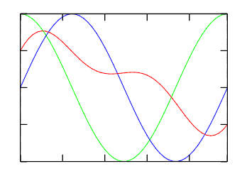 |
(3 plots) BOX=Yes |
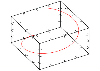 |
ROTATE=40:0:60 BOX=Yes |
MARK
Draws a mark in each point. DS_COLOR, DS_MARKSTYLE and DS_MARKSIZE are used to configure the marks.
MARKLINE
Draws lines between points and draws a mark in each point. Same as if LINE and MARK where set together.
RADAR
Draws a radar chart. Like a LINE plot in polar coordinates. RADARSHIFT configures an additional radial shift of the data [If rs<0 then rs=max(0, -min(a))], default=-1. If DATAGRID=Yes then a grid of radial lines and a circle for rs are drawn. DS_COLOR, DS_LINESTYLE and DS_LINEWIDTH are used to configure the lines. DS_COLOR, DS_MARKSTYLE and DS_MARKSIZE are used to configure the marks.
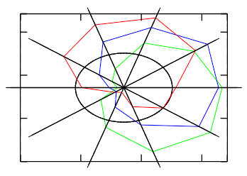 |
(3 plots) RADARSHIFT=0.4 DATAGRID=Yes BOX=Yes |
AREA
Draws lines between points and fills it to axis plane. DS_COLOR is used to configure fill color. The order of the datasets will define which one will be drawn first.
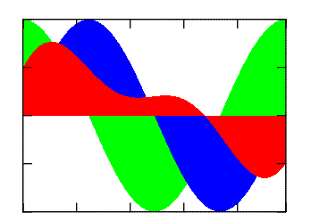 |
(3 plots) AXS_XORIGIN=0 AXS_YORIGIN=0 BOX=Yes |
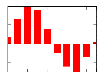
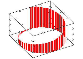
BAR
Draws vertical bars from points to axis plane. If DATAGRID=Yes then grid lines are drawn, default=No. BARWIDTH sets relative width of rectangles, default=0.7.
 |
AXS_XORIGIN=0 AXS_YORIGIN=0 BOX=Yes |
 |
ROTATE=40:0:60 BOX=Yes |
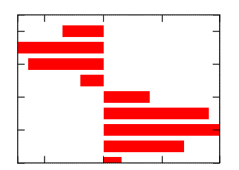
BARHORIZONTAL
Draws horizontal bars from points to axis plane. If DATAGRID=Yes then grid lines are drawn, default=No. BARWIDTH sets relative width of rectangles, default=0.7.
 |
AXS_XORIGIN=0 AXS_YORIGIN=0 BOX=Yes |
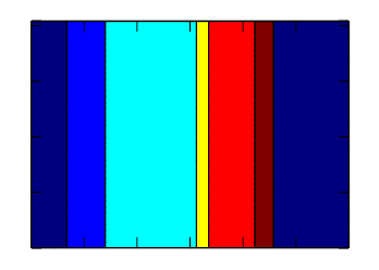
CHART
Draws colored stripes (boxes). If DATAGRID=Yes then black border lines are drawn, default=No. If PIECHART=Yes cylindrical coordinates are used, default=No.
 |
DATAGRID=Yes BOX=Yes |
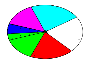 |
DATAGRID=Yes BOX=Yes PIECHART=Yes COLORSCHEME=bgr cmy |
STEP
Draws continuous stairs for points to axis plane. DS_COLOR, DS_LINESTYLE and DS_LINEWIDTH are used to configure the lines. DS_COLOR, DS_MARKSTYLE and DS_MARKSIZE are used to configure the marks.
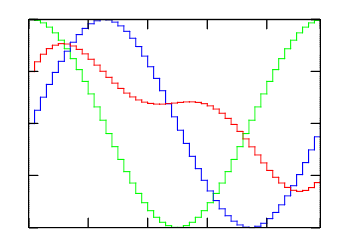 |
(3 plots) BOX=Yes |
STEM
Draws vertical lines from points to axis plane. DS_COLOR, DS_LINESTYLE and DS_LINEWIDTH are used to configure the lines. DS_COLOR, DS_MARKSTYLE and DS_MARKSIZE are used to configure the marks.
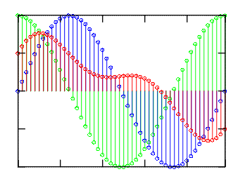 |
(3 plots) DS_MARKSTYLE=HOLLOW_CIRCLE DS_SHOWMARKS=Yes AXS_XORIGIN=0 AXS_YORIGIN=0 BOX=Yes |
DOTS
Draws arbitrary placed points. Colors will be used from the previous color scheme or from COLORSCHEME if defined.
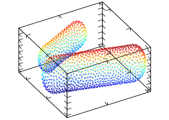 |
ROTATE=40:0:60 BOX=Yes TRANSPARENT=No LIGHT=Yes |
CRUST
This will reconstruct and draw the surface for arbitrary placed points. Parameter CRUSTRADIUS set relative radius (increase it for removing holes), default=0. If DATAGRID=Yes then wire plot is produced, default=No. Colors will be used from the previous color scheme or from COLORSCHEME if defined.
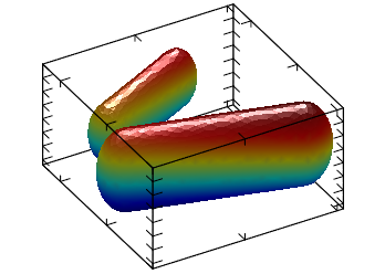 |
ROTATE=40:0:60 BOX=Yes TRANSPARENT=No LIGHT=Yes |
For Planar Datasets
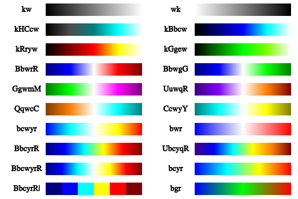
For all planar modes colors will be used from the previous color scheme or from COLORSCHEME if defined. COLORSCHEME is a string that can specify a group of colors to be used by the plot.
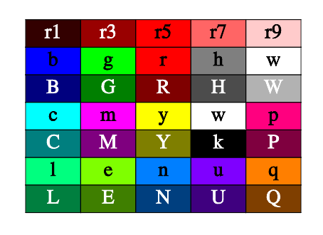
Colors in a color scheme are specified by the codes "wkrgbcymhRGBCYMHWlenupqLENUPQ" only. A brightness weight from 1 to 9 can also be used to change the default value from 5 normal, to 1 very dark, and to 9 very bright.
Also the symbol d denotes the interpolation by 3D position instead of the coloring by amplitude. Symbol | disables color interpolation in color scheme, which can be useful, for example, for sharp colors during matrix plotting.
For coloring by amplitude (most common) the final color is a linear interpolation of color array. The color array is constructed from the string ids. The argument is the amplitude normalized based on COLORBARRANGE. When coloring by coordinate, the final color is determined by the position of the point in 3D space and is calculated from combining the first three elements of color array with the x, y and z normalizes values. This type of coloring is useful for isosurface plot where color may show the exact position of a piece of surface.
Here are some examples or color codes and color schemes:
PLANAR_MESH
Draws mesh lines for the surface. Mesh lines are plotted for each z slice of the data. DS_LINESTYLE and DS_LINEWIDTH are used to configure the lines.
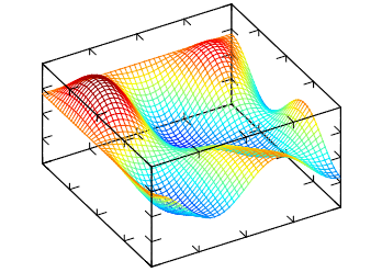 |
ROTATE=40:0:60 BOX=Yes TRANSPARENT=No LIGHT=Yes |
PLANAR_FALL
Draws fall lines for the surface. DS_LINESTYLE and DS_LINEWIDTH are used to configure the lines. If DIR=X, then lines are drawn along x-direction else lines are drawn along y-direction, default=Y.
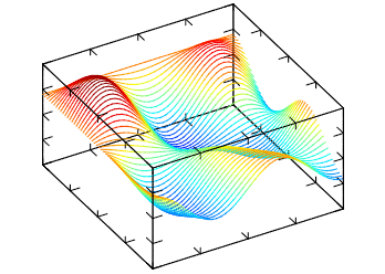 |
ROTATE=40:0:60 BOX=Yes TRANSPARENT=No LIGHT=Yes |
PLANAR_BELT
Draws belts for the surface. If DIR=X, then lines are drawn along x-direction else lines are drawn along y-direction, default=Y.
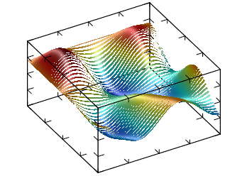 |
ROTATE=40:0:60 BOX=Yes TRANSPARENT=No LIGHT=Yes |
PLANAR_SURFACE
Draws the surface. If DATAGRID=Yes then grid lines are drawn, default=No.
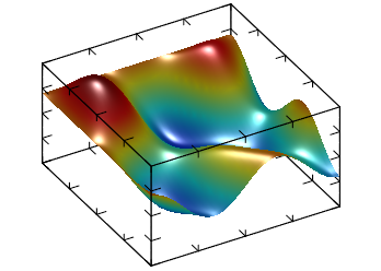 |
ROTATE=40:0:60 BOX=Yes TRANSPARENT=No LIGHT=Yes |
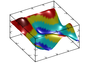 |
ROTATE=40:0:60 BOX=Yes TRANSPARENT=No LIGHT=Yes COLORSCHEME=BbcyrR| |
PLANAR_BOXES
Draws vertical boxes for the surface. If DATAGRID=Yes then box lines are drawn, default=No.
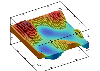 |
ROTATE=40:0:60 BOX=Yes TRANSPARENT=No LIGHT=Yes AXS_XORIGIN=0 AXS_YORIGIN=0 AXS_ZORIGIN=0 |
PLANAR_TILE
Draws horizontal tiles for the surface, it can be seen as 3D generalization of STEP.
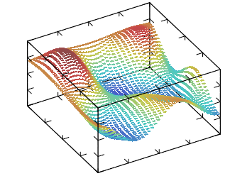 |
ROTATE=40:0:60 BOX=Yes TRANSPARENT=No LIGHT=Yes |
PLANAR_DENSITY
Draws density plot for the surface at a specified z coordinate. PLANARVALUE specifies the z coordinate, if not defined AXS_ZMIN is used.
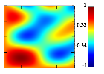 |
BOX=Yes TRANSPARENT=No COLORBAR=Yes |
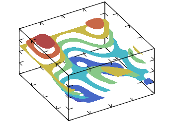
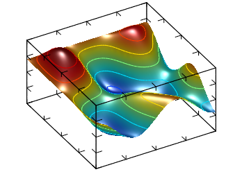
PLANAR_CONTOUR
Draws contour lines for the surface at a z coordinate. CONTOURCOUNT defines the number of contour lines, default=7. PLANARVALUE specifies a z coordinate, if not defined contours are distributed in the COLORBARRANGE interval. If CONTOURFILLED=Yes draws solid (or filled) contour lines for the surface, default=No. If CONTOURLABELS is defined then contour labels will be drawn BELLOW or ABOVE the contours.
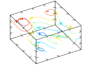 |
ROTATE=40:0:60 BOX=Yes TRANSPARENT=No LIGHT=Yes CONTOURLABELS=BELLOW |
 |
ROTATE=40:0:60 BOX=Yes TRANSPARENT=No LIGHT=Yes CONTOURFILLED=Yes |
 |
ROTATE=40:0:60 BOX=Yes TRANSPARENT=No LIGHT=Yes (dual plot) DS_MODE=PLANAR_SURFACE DS_MODE=PLANAR_CONTOUR |
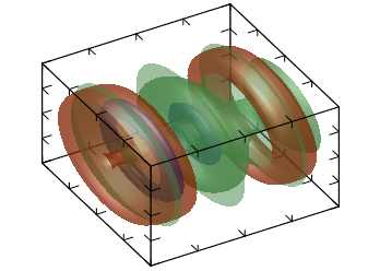
PLANAR_AXIALCONTOUR
Draws a surface which is result of the contour plot rotation for the surface. AXIALCOUNT defines the number of elements distributed in the COLORBARRANGE interval, default=3.
 |
ROTATE=40:0:60 BOX=Yes TRANSPARENT=Yes LIGHT=Yes |
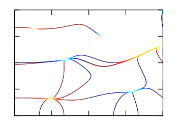
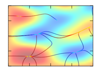
PLANAR_GRADIENTLINES
Draws gradient lines for scalar field defined by the surface at a specified z coordinate. PLANARVALUE specifies the z coordinate, if not defined AXS_ZMIN is used. Number of lines is proportional to GRADLINESCOUNT, default=5 . If GRADLINESCOUNT<0 then lines start from borders only. Lines are plotted for each z slice of the data.
 |
BOX=Yes TRANSPARENT=Yes LIGHT=Yes |
 |
BOX=Yes TRANSPARENT=Yes LIGHT=Yes (dual plot) DS_MODE=PLANAR_GRADIENTLINES DS_MODE=PLANAR_DENSITY |
For Volumetric Datasets
For all volumetric modes colors will be used from the previous color scheme or from COLORSCHEME if defined.
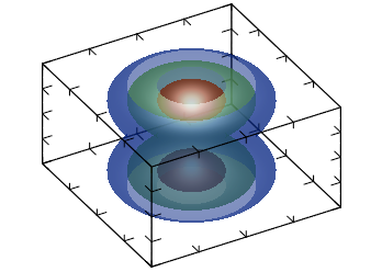
VOLUME_ISOSURFACE
Draws isosurface plot for the volume. If DATAGRID=Yes then wire plot is produced, default=No. if ISOVALUE is defined only 1 isosurface is plot, else ISOCOUNT (default=3) surfaces are plot distributed in the COLORBARRANGE interval.
Note, that there is possibility of incorrect plotting due to uncertainty of cross-section defining if there are two or more isosurface intersections inside one cell.
 |
ROTATE=40:0:60 BOX=Yes TRANSPARENT=Yes LIGHT=Yes |
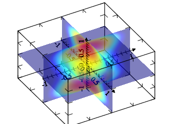
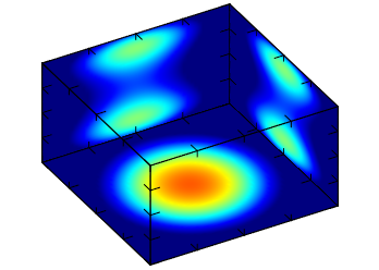
VOLUME_DENSITY
Draws density plot for the volume. If DATAGRID=Yes then grid lines are drawn, default=No. If PROJECT=Yes draws density plot in x, y, or z plain, default=No. When PROJECT=Yes, PROJECTVALUEX, PROJECTVALUEY and PROJECTVALUEZ, are used to select data at the given coordinate, if they are not defined AXS_?ORIGIN is used accordingly. When PROJECT=No, SLICEX, SLICEY and SLICEZ, are used to define the slice where the plot is done, default is -1 (central). SLICEDIR defines which directions are used, default "XYZ".
 |
ROTATE=40:0:60 BOX=Yes TRANSPARENT=Yes LIGHT=No AXS_XORIGIN=0 AXS_YORIGIN=0 AXS_ZORIGIN=0 AXS_X=Yes AXS_Y=Yes AXS_Z=Yes |
 |
ROTATE=40:0:60 BOX=Yes TRANSPARENT=No LIGHT=No PROJECT=Yes PROJECTVALUEX=-1 PROJECTVALUEY=1 PROJECTVALUEZ=-1 |
VOLUME_CONTOUR
Draws contour plot for the volume. If DATAGRID=Yes then grid lines are drawn, default=No. If PROJECT=Yes draws contour plot in x, y, or z plain, default=No. When PROJECT=Yes, PROJECTVALUEX, PROJECTVALUEY and PROJECTVALUEZ, are used to select data at the given coordinate, if they are not defined AXS_?ORIGIN is used accordingly. When PROJECT=No, SLICEX, SLICEY and SLICEZ, are used to define the slice where the plot is done, default is -1 (central). SLICEDIR defines which directions are used, default "XYZ". If CONTOURFILLED=Yes draws solid (or filled) contour lines for the surface, default=No. CONTOURCOUNT defines the number of contour lines, default=7. Where lines are used, DS_LINESTYLE and DS_LINEWIDTH are used to configure the lines.
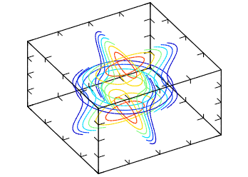 |
ROTATE=40:0:60 BOX=Yes TRANSPARENT=No LIGHT=Yes |
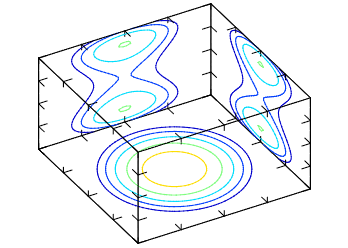 |
ROTATE=40:0:60 BOX=Yes TRANSPARENT=No LIGHT=Yes PROJECT=Yes PROJECTVALUEX=-1 PROJECTVALUEY=1 PROJECTVALUEZ=-1 |
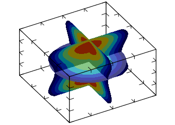 |
ROTATE=40:0:60 BOX=Yes TRANSPARENT=No LIGHT=Yes |
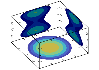 |
ROTATE=40:0:60 BOX=Yes TRANSPARENT=No LIGHT=Yes PROJECT=Yes PROJECTVALUEX=-1 PROJECTVALUEY=1 PROJECTVALUEZ=-1 CONTOURFILLED=Yes |
VOLUME_CLOUD
Draws cloud plot for the volume. This plot is a set of cubes with color and transparency proportional to value of ALPHA. The resulting plot is like cloud low value is transparent but higher ones are not. If CLOUDCUBES=No the semi-transparent points are used instead of cubes, default=Yes.
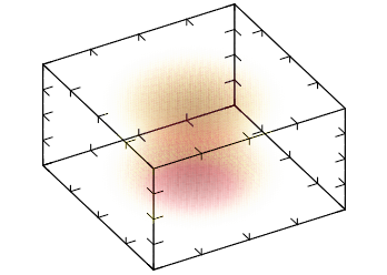 |
ROTATE=40:0:60 BOX=Yes TRANSPARENT=Yes LIGHT=No COLORSCHEME=wyrRk CLOUDCUBES=No |
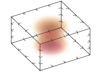 |
ROTATE=40:0:60 BOX=Yes TRANSPARENT=Yes LIGHT=No COLORSCHEME=wyrRk |
Known Issues
Selection and editing of a dataset using the DS_EDIT attribute are not implemented.
Automatic ticks computation needs to be improved.
BOLD and ITALIC styles are not working inside TeX formatting.
There is still lots of MathGL features not available in IUP::MglPlot.
When OPENGL=Yes and ANTIALIAS=Yes, 3D graphs will not process depth properly. (OpenGL configuration?)
When OPENGL=Yes, Graph is disappearing during zoom in, after a zoom factor. Maybe a depth clipping problem. (OpenGL configuration?)
When OPENGL=Yes, Legend box is not being displayed. (MathGL)
When OPENGL=Yes aspect ratio of text and marks are not respected.(MathGL)
The control of ticks being oriented inside or outside the graph is not working. (MathGL)
Bar graph is clipped at 0 and at n-1. (MathGL)
When tick labels are specified all ticks are displayed regardless of tick spacing configuration. (MathGL)
Axis color is always drawn in black. (MathGL)
EXAMPLES
The element IUP::MglPlot is used in the following sample scripts:
0-basic/mglplot1.pl - IUP::MglPlot example
1-apps/app-plot-demo.pl - dials for zooming
SEE ALSO
The original doc: iup_mglplot.html, <iup_mglplot_modes.htm|http://www.tecgraf.puc-rio.br/iup/en/ctrl/iup_mglplot_modes.html>